
Location: Computational Engineering & Robotics Lab (CERLAB), CMU, PA
Timeframe: Fall 2024 – Present
Advisor: Professor Kenji Shimada
Target Publication: IEEE Robotics and Automation Letters (RA-L), March 2026
Introduction
Additive manufacturing for construction reduces material waste, shortens build timelines, and enables novel architectural forms. Within construction-scale AM, spray-based concrete deposition (shotcrete) offers distinct advantages over extrusion methods: the increased nozzle-to-substrate standoff distance permits continuous printing over pre-positioned reinforcement bars without specialized nozzles or print-pause-insert sequences.
However, spray deposition introduces unique trajectory planning challenges. Unlike extrusion where the toolpath directly defines deposited geometry, spray involves stochastic particle trajectories and material spreading behavior. The nozzle position, orientation, and velocity must be coordinated to achieve uniform coverage while maintaining motion feasibility for the gantry system.
This research develops a comprehensive nozzle trajectory planning methodology for spray-based concrete 3D printing of complex freeform structures with embedded rebar. The objective is to autonomously generate trajectories that minimize non-productive gantry motion while ensuring consistent material deposition across varying geometric complexity.
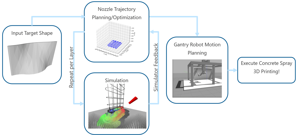
The concrete spray 3D printing pipeline: nozzle trajectory planning feeds into simulation, which provides feedback for iterative refinement before gantry robot motion planning and execution
Design & Development
My role: Primary researcher responsible for algorithm development, C++ implementation, and experimental validation for nozzle trajectory path planning. Professor Shimada provides research direction and Shimizu Corporation supplies industry test geometries.
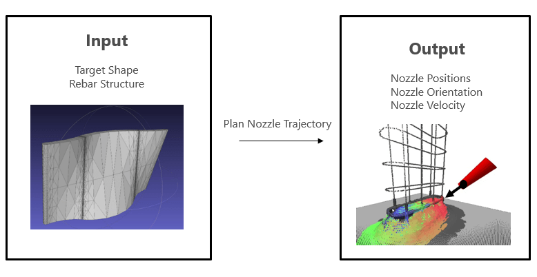
The trajectory planning methodology operates through four sequential phases, transforming an input STL mesh into executable nozzle waypoints with positions, orientations, and velocities.
Phase 1: Geometric Preprocessing
The target mesh is sliced at discrete layer heights to extract closed contour polygons. For each slice, edge-plane intersections compute the boundary vertices and corresponding surface normals. For structures exceeding the effective spray deposition width, inner contours are generated via geometric insetting using bisector-based offset computation to enable multi-pass coverage while preserving facet normals.
Phase 2: Path Standardization
Extracted contours are standardized with consistent traversal direction and anchor points. This ensures predictable behavior for downstream processing—inner loops traverse clockwise while outer loops traverse counter-clockwise, with transitions occurring at leftmost points.
Phase 3: Waypoint Refinement
Uniform material coverage requires consistent spacing between waypoints. Given a user-defined spray radius, the contour is resampled via arc-length parameterization using a distributed remainder algorithm. This produces waypoints spaced at the target interval (e.g., 10mm) with minimal deviation (standard deviation ≈ 0.033mm across all test geometries).
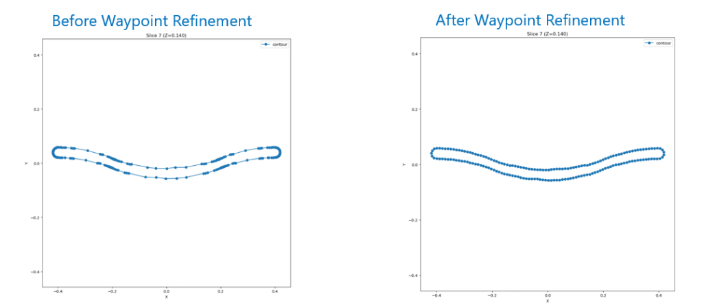
Left: Initial sparse vertices from mesh-plane intersection. Right: Uniformly distributed waypoints after arc-length resampling.
Phase 4: Trajectory Optimization — Core Contributions
The primary technical contributions focus on two coupled problems: (1) reducing the waypoints requiring full orientation computation while preserving geometric fidelity, and (2) computing nozzle orientations that minimize gantry base angular displacement.
Adaptive Sampling for Computational Efficiency
Rather than computing orientations for every waypoint, a subset is adaptively sampled based on spatial and angular criteria. A waypoint is marked as sampled if:
- Distance from previous sampled point exceeds spatial threshold (200mm)
- Surface normal change exceeds angular threshold (15°)
Special guards ensure first/last waypoints are always sampled and no two consecutive waypoints are sampled. This typically reduces the orientation computation set by 80-90% while capturing all geometric features.
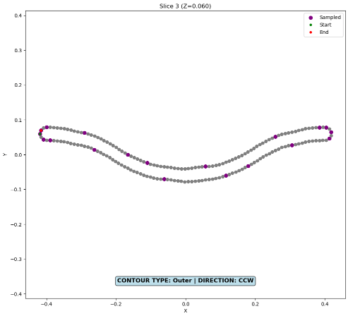
Sampled waypoints (magenta) concentrate at high-curvature regions and contour extremities, while straight sections require minimal samples.
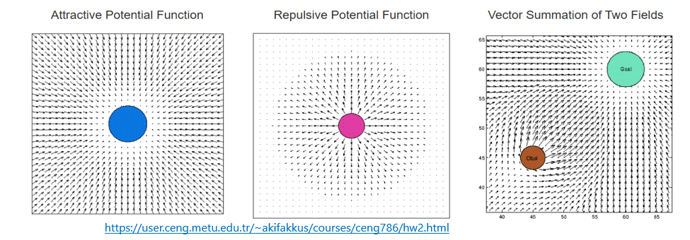
Potential Field-Based Orientation Planning
The key insight is that nozzle orientations aligned purely with surface normals (the conventional approach) cause excessive gantry base rotation as the nozzle traverses the contour. Instead, orientations can be biased toward a consistent direction to reduce cumulative angular displacement.
The method combines two vector fields:
- Repulsive field: Surface normal direction (pointing away from the deposition surface)
- Attractive field: Direction toward a strategically placed source point (rightmost point closest to vertical center)
Two-Pass Orientation Strategy:
Pass 1 — Direct Attraction: For non-degenerate waypoints (where surface normal and attraction direction are not nearly parallel), the orientation is computed by distance-weighted blending:
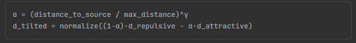
The blending parameter α increases with distance from the source, causing waypoints farther away to experience stronger attraction toward the source. This produces the characteristic “tilting toward sink” behavior.
Pass 2 — Perpendicular Rotation: Degenerate waypoints (where direct blending would produce unstable results) are handled iteratively using perpendicular rotation guided by neighboring sampled waypoints. The algorithm selects the perpendicular direction with higher alignment to already-processed neighbors.
SLERP Interpolation for Smooth Transitions
Orientations for non-sampled waypoints are computed via spherical linear interpolation (SLERP) between adjacent sampled orientations. This ensures constant angular velocity and kinematically feasible motion throughout the trajectory.
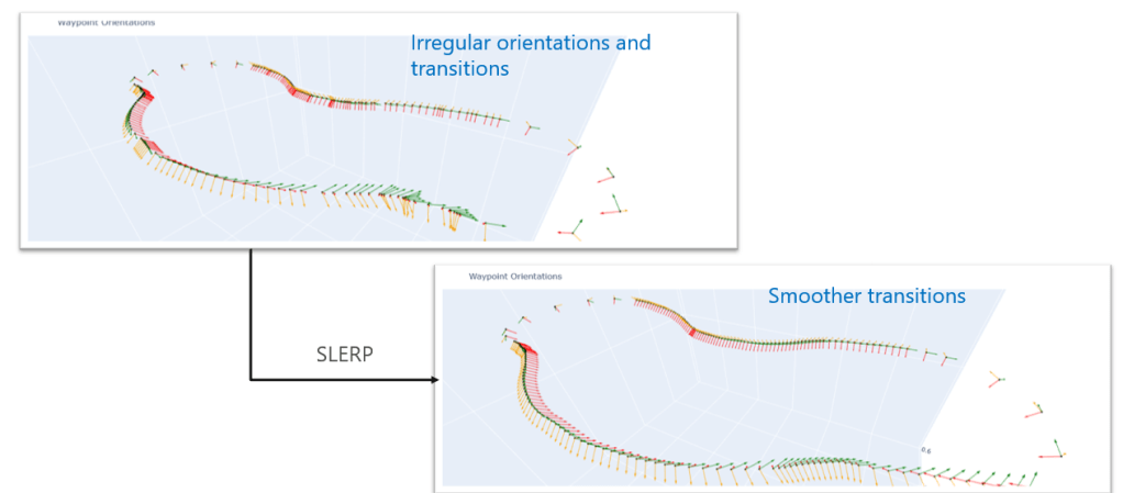
Top: Irregular orientations and abrupt transitions before SLERP. Bottom: Smooth, consistent transitions after SLERP interpolation between sampled waypoints.
Evaluation
The methodology was validated on four representative geometries with increasing structural complexity: Cylinder (rotational symmetry), Wall-S (planar multi-bar), J-Shape (varying curvature), and Complex Rebar Network (3D intersecting bars).
Tilt Angle Characterization
The cylinder test case demonstrates the distance-weighted blending behavior. Plotting nozzle tilt angle versus distance from the attractive source reveals linear relationships:
- Start-to-Attractive segment: slope = 68.27°/m
- Attractive-to-End segment: slope = 76.00°/m
This confirms the theoretical formulation: waypoints farther from the source experience greater orientation tilt, progressively biasing the nozzle toward the consistent angular direction.
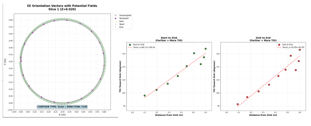
Linear increase in tilt angle with distance from attractive source validates the α(d) = (d/dmax)^γ blending mechanism.
Robustness Across Geometries
The potential field method generalizes across symmetric and asymmetric shapes without modification. Testing on Wall-S and J-Shape geometries shows consistent tilting behavior regardless of contour complexity. The two-pass system handles degenerate cases (waypoints directly aligned with or opposite to the attraction direction) gracefully through the neighbor-guided perpendicular rotation strategy.
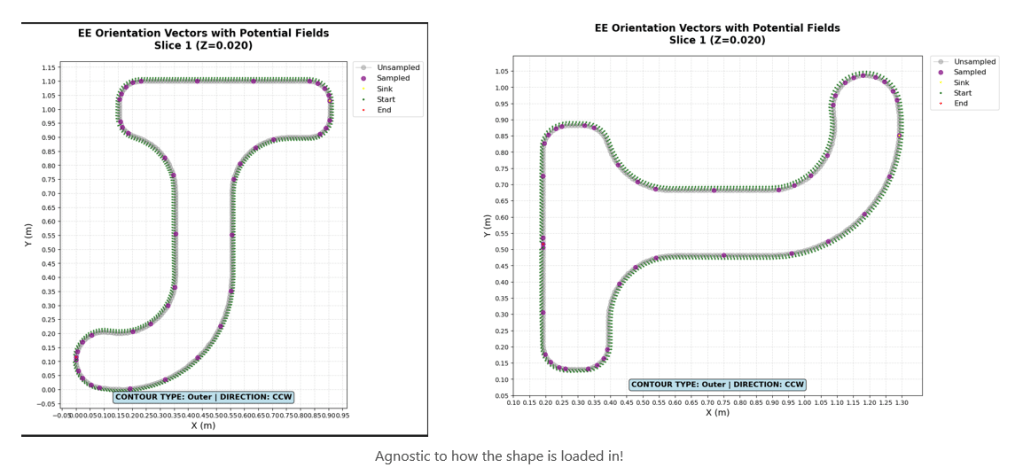

EE orientation vectors with potential fields for Wall-S (left) and J-Shape (right). All waypoints tilt appropriately toward the Attractive point (labeled sink) regardless of shape geometry
Industry Validation: HS7 Structure
The methodology was applied to the HS7 freeform structure provided by industry partner Shimizu Corporation. The complex curved geometry with embedded rebar network successfully processed through all pipeline stages, producing smooth orientation transitions across 100+ print layers.
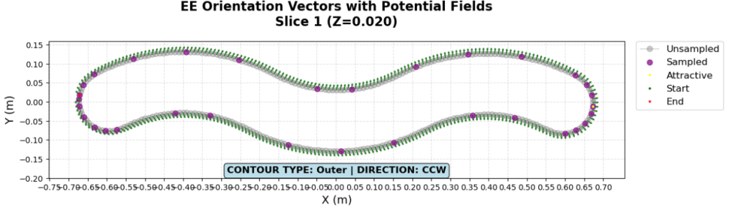
HS7 Structure: EE Orientation vectors showing consistent tilting behavior through the curved freeform geometry
Full simulation prints demonstrate the nozzle following contour outlines with alternating clockwise/counter-clockwise traversal between each layer at a constant velocity. The resulting deposited geometry (exported as STL) shows successful coverage of the rebar structure.

Left: Simulation of HS7 print in progress with rebar structure. Right: Post-print STL showing material deposition around reinforcement.
Conclusion
This research presents a trajectory planning methodology for spray-based concrete 3D printing that addresses the unique challenges of stochastic material deposition over complex reinforcement structures. The key contributions—adaptive sampling for computational efficiency and potential field-based orientation optimization for motion feasibility—enable autonomous trajectory generation across diverse freeform geometries.
The distance-weighted potential field formulation provides intuitive control over the tradeoff between surface-normal alignment (for deposition quality) and consistent angular direction (for gantry efficiency). The two-pass strategy with SLERP interpolation ensures kinematically feasible trajectories without manual tuning per geometry.
Ongoing work focuses on simulation-driven adaptive velocity control, where feedback from computational spray deposition models will inform nozzle speed adjustments to compensate for process stochasticity. This closed-loop approach will enable trajectory refinement based on accumulated material geometry versus target specifications.
This project has developed my expertise in computational geometry (mesh processing, contour extraction, arc-length parameterization), trajectory optimization (potential fields, interpolation methods), and the integration of planning algorithms with physical manufacturing constraints. The methodology generalizes beyond concrete printing to any spray-based coating or deposition application requiring coordinated multi-axis motion planning.
