
Location: Computational Engineering & Robotics Lab (CERLAB), CMU, PA
Timeframe: Fall 2024 – Present
Advisor: Professor Kenji Shimada
Target Publication: IEEE Robotics and Automation Letters (RA-L), August 2026
Introduction
Spray-based concrete 3D printing at Shimizu Corporation, Tokyo. The in-progress print shows the uneven material accumulation and surface irregularity around rebar that this work addresses.
Construction-scale additive manufacturing reduces build time and cost by eliminating traditional formwork. Spray-based concrete deposition (Shotcrete 3D Printing, SC3DP) offers a distinct advantage over extrusion: a standoff distance that allows continuous deposition directly over pre-positioned reinforcement bars (rebar), which extrusion cannot do without collision risk.
That advantage comes with a planning challenge. Sprayed concrete behaves stochastically. Dripping, particle rebound, and airflow-driven spreading cause material to accumulate unevenly across the layer footprint rather than at the planned height, and concrete sprayed over rebar clumps further. Current trajectory planning methods do not account for the prior layer’s uneven accumulation when planning nozzle velocity. Each new layer is planned as if the layer beneath it deposited uniformly, so errors propagate and amplify, and the deposited shape drifts progressively from the target. This drift is most consequential for complex freeform structures, where each layer’s cross-section differs from the last and errors accumulate visibly rather than averaging out as they do in self-similar walls or pillars.
Addressing this requires two coupled capabilities: simulation-driven nozzle velocity planning that adapts to the accumulated geometry of prior layers, and feasibly executable nozzle orientations that let the robotic system traverse the structure without abrupt orientation changes. Without smooth orientations the trajectory is rejected or run at reduced velocity, which makes the velocity plan ineffective regardless of how good the deposition model is. This research delivers both within a single pipeline.
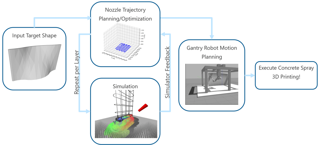
The concrete spray 3D printing pipeline: nozzle trajectory planning feeds into simulation, which provides feedback for iterative refinement before gantry robot motion planning and execution
Design & Development
My role: Primary researcher responsible for algorithm development, C++ implementation, and experimental validation of the nozzle trajectory planning pipeline. Professor Shimada provides research direction. Shimizu Corporation supplies the industry test geometry.
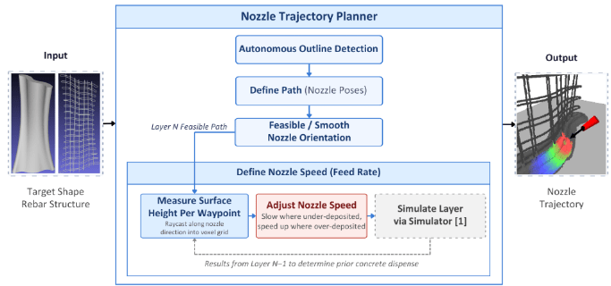
Overview of the proposed pipeline. A target rebar geometry and a prior-layer voxel grid are transformed into a full layer-by-layer set of nozzle trajectories through four sequential stages.
The pipeline takes a target rebar geometry (a triangulated surface mesh) and a voxel grid of accumulated material from prior layers, where each voxel is labeled concrete, rebar, or air, and produces a full layer-by-layer set of nozzle trajectories executable on any robotic system. Each waypoint carries a position, an orientation, and a velocity. The four stages run in sequence.
Stage 1: Autonomous Outline Detection
For each layer, the target mesh is sliced at midpoint height to extract the surface contour, while waypoint positions are locked to the true layer top. Slicing at the midpoint avoids degenerate cases where the plane coincides with horizontal cap faces. An edge-traversal algorithm walks polygon to polygon through the mesh, computing exact edge-plane intersection points by linear interpolation and recording the facet normal at each intersection. For structures whose wall thickness exceeds the spray footprint, an optional inner contour is generated by per-vertex bisector insetting to enable multi-pass coverage.
Stage 2: Nozzle Pose Definition
Contour vertices from mesh triangulation are non-uniformly spaced, so the contour is standardized before use. Counter-clockwise winding is enforced from the leftmost vertex for consistent traversal across all layers, surface normals are smoothed by three iterations of Laplacian averaging (lambda = 0.5) to reduce faceting noise, and the contour is densified and resampled at uniform arc-length intervals with any remainder distributed evenly so spacing stays consistent around the closed loop. Each waypoint is assigned an initial spray direction equal to its surface normal. Successive layers alternate traversal direction to minimize non-printing travel at layer transitions.
Stage 3: Feasible and Smooth Nozzle Orientation Planning
Surface-normal orientations are the conventional default, but they are computed independently at each waypoint and can produce transitions that are smooth in workpiece coordinates yet sharp in robot coordinates, forcing the motion planner to reject the trajectory or execute it at reduced velocity. Because reduced velocity would invalidate the layer-adaptive velocity plan computed downstream, producing executable orientation sequences is a precondition for velocity adaptation, not an end in itself. This stage produces smooth, executable orientations and, as a secondary benefit, reduces overall articulation along the trajectory.
Key waypoint selection. Rather than optimizing every waypoint, the framework selects only the geometrically significant ones, where the contour exhibits its largest simultaneous changes in position and surface normal direction (position change above a 100 mm spatial threshold and normal change above a 15 degree angular threshold). First and last waypoints are always included.
Potential field orientation (two-pass). Each selected waypoint is biased toward a common attractive source (the rightmost selected waypoint, ties broken by proximity to the vertical midpoint) to reduce cumulative articulation. Pass 1, direct attraction: non-degenerate waypoints blend their end-effector direction toward the source with a distance-based weight, so waypoints farther from the source tilt more strongly toward it. Pass 2, perpendicular rotation: degenerate waypoints, where direct blending is unstable, are rotated toward the perpendicular better aligned with already-processed neighbors.
SLERP interpolation and downward tilt. Orientations for non-selected waypoints are filled by spherical linear interpolation between adjacent key-waypoint quaternions (built via Shepperd’s method), giving constant angular velocity and smooth transitions. All waypoints then receive a uniform 45 degree downward tilt toward the deposition surface.
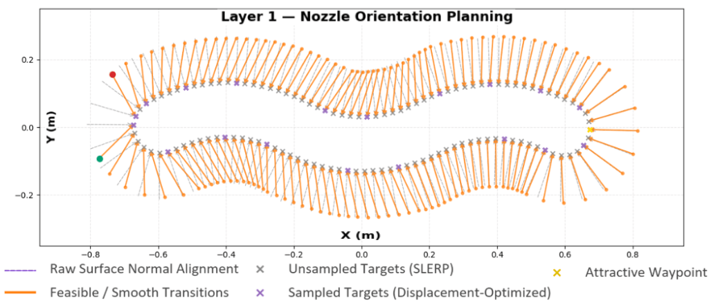
Planned orientation field at a representative layer. Orange vectors are the displacement-optimized orientations from the potential field framework with SLERP interpolation; dashed gray lines are the raw surface normals. Purple crosses mark the key waypoints selected for optimization, gray crosses the SLERP-interpolated intermediates, and the yellow cross the attractive source.
Stage 4: Simulation-Driven Nozzle Velocity Adaptation
This stage is the central contribution of the work. It plans nozzle velocity layer by layer from the accumulated geometry of prior layers. At each finalized waypoint, a ray marches along the spray direction into the prior-layer voxel grid (produced by the SC3DP simulator of Yamakawa et al.) in 1 mm steps. The first concrete voxel hit gives the accumulated surface height, and the material deficit (target layer top minus measured surface) is the vertical gap the next pass must close. A positive deficit means under-deposition.
Deficits across the layer are normalized and mapped inversely to velocity: the nozzle slows where coverage is thin to dispense more material, and speeds up where buildup is excessive to dispense less. A near-target threshold assigns maximum velocity directly when a waypoint is already close to target, which prevents the per-layer normalization from amplifying noise-level surface variation into large velocity swings. Because the deficit range is recomputed per layer, the mapping is scale-free with respect to that layer’s overall coverage. The first layer, with no prior deposition, is initialized at the midpoint velocity. Velocity parameters based on Shimizu’s testing experience were set to: minimum 20 mm/s, maximum 35 mm/s, near-target threshold 10 mm.
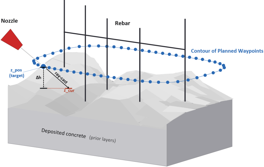
Velocity measurement geometry. At each planned waypoint, a ray is cast along the spray direction into the prior-layer voxel grid. The first concrete voxel hit returns the accumulated surface height, and the deficit between target and measured height sets the nozzle velocity inversely.
Evaluation Setup
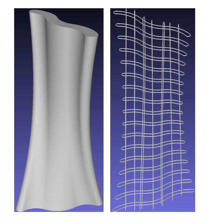
The method is evaluated on a complex freeform architectural rebar structure provided by Shimizu Corporation (the HS7 structure), a real construction-relevant geometry the company intends to fabricate using SC3DP. The rebar structure (1250 x 1090 x 2560 mm) is a dense three-dimensional network of intersecting bars; the target concrete form (1360 x 1200 x 2500 mm) encloses it. Both are provided as triangulated surface meshes.
Two baselines isolate the two contributions. A velocity baseline traverses at a fixed 35 mm/s regardless of prior-layer surface state, isolating the simulation-driven velocity adaptation. An orientation baseline sets orientations directly to the surface normal at each waypoint, isolating the efficiency benefit of the potential field orientation framework.
Results
Feasible, Executable Poses
The planned trajectory must be physically executable by the robotic system that carries it out. Two results establish this.
First, executability. The mean quaternion trajectory across the layer contour evolves as four smooth, continuous curves in both clockwise and counter-clockwise traversal, with no abrupt jumps. Narrow envelopes across 42 CW and 42 CCW layers confirm the orientation plan is repeatable regardless of traversal direction. Because the failure mode (rejected or velocity-reduced trajectories) is triggered by exactly such discontinuities, their absence preserves the validity of the velocity plan at execution time.
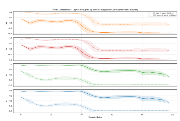
Mean quaternion trajectory versus waypoint index for clockwise (solid) and counter-clockwise (dashed) traversal. Each panel plots one quaternion component. Shaded envelopes show standard deviation across layers.
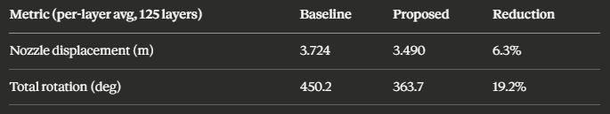
Second, efficiency. Relative to the surface-normal baseline, the orientation framework reduces nozzle displacement by 6.3% (3.724 to 3.490 m) and total rotation by 19.2% (450.2 to 363.7 degrees) per layer on average across 125 layers. Shorter Cartesian paths and smaller cumulative rotations translate directly into less motion per layer for whatever robotic system executes the trajectory.
Simulation-Driven Velocity Adaptation
This is the central result, evaluated on the Shimizu structure against the constant-velocity baseline.
At an early layer, the constant-velocity baseline already shows spatially non-uniform deposition: under-deposition along the center of the contour path and pronounced ridges at the flanks, where tight geometric turns cause the fixed-velocity nozzle to over-accumulate. The adaptive method corrects both, slowing the nozzle in the under-deposited center to dispense more material and speeding it up at the over-accumulated flanks to dispense less.
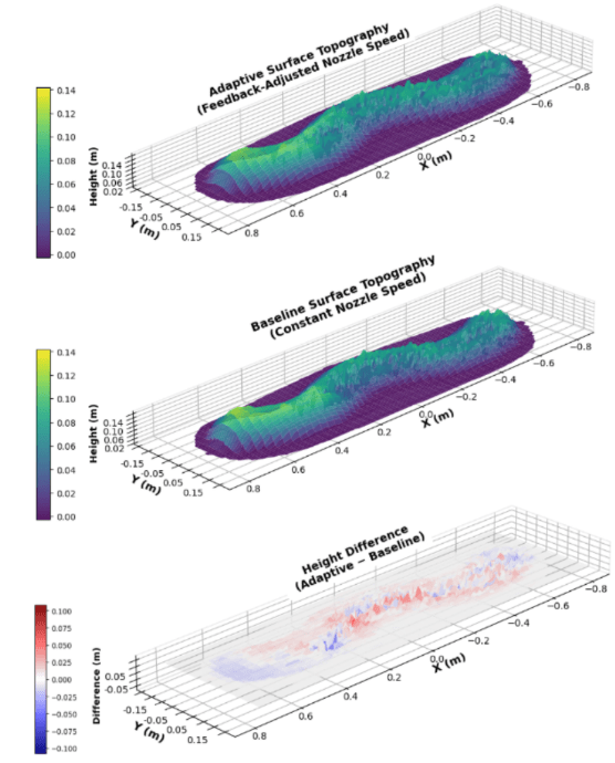
Simulated surface topography at layer 5. Top: adaptive velocity method. Middle: constant-velocity baseline. Bottom: pointwise height difference (adaptive minus baseline); red indicates greater deposition, blue indicates lesser, relative to the baseline.
Tracked across 100 layers, these patterns do not self-correct without adaptive control. The baseline’s uneven regions become the irregular surface from which the next layer is planned, propagating and amplifying the same deposition errors forward. The adaptive planner reads the actual prior-layer surface and compensates for each layer’s true state, reducing surface height standard deviation by 28.4% on average (baseline 39.23 mm, adaptive 28.08 mm), with improvement across all sampled layers. This is the precision result.
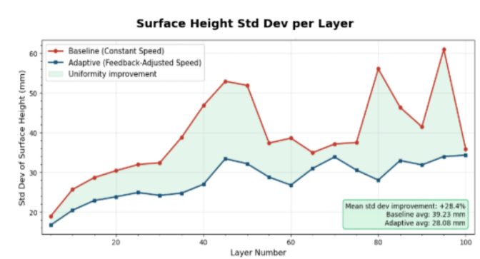
Surface height standard deviation per sampled layer for the adaptive method (blue) and constant-velocity baseline (red). The shaded region indicates layers where the adaptive method achieves lower variation.
A second measure captures accuracy: how much of the target shape each layer actually fills. Cumulative coverage reaches 98.2% of the target shape versus 97.5% for the baseline. The more discriminative per-layer coverage, which scores each layer once the next has settled, averages 75.9% versus 67.3%, a 12.8% relative improvement. Together, precision and accuracy confirm the feedback loop operates as a persistent corrective mechanism across the full 125-layer print, directly preventing the progressive drift identified in the introduction.
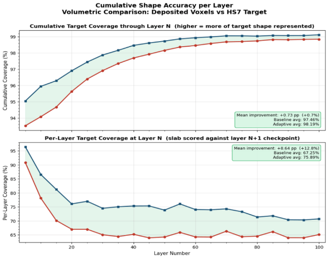
Cumulative (top) and per-layer (bottom) target shape coverage for the adaptive method (blue) and baseline (red). Shaded regions indicate the adaptive method’s improvement.
Structural Fidelity of the Printed Form
The full 125-layer simulated print fully encapsulates the Shimizu rebar structure at every layer. Mean wall thickness is 26.3 mm (minimum 3.3 mm at the structure apex, maximum 64.6 mm at the mid-section). The mean thickness confirms that the 28.4% uniformity gain is not achieved by globally adding material: the adaptive planner redistributes deposition based on prior-layer state while maintaining structurally sufficient coverage. Residual thickness variation reflects the target geometry and is addressed by subtractive surface finishing, standard practice for SC3DP freeform fabrication.
One current limitation affects a specific geometric regime. Voids can form in interior zones geometrically occluded by rebar, where the rebar blocks spray from reaching the region behind it. The pipeline currently relies on passive material spreading to partially fill these gaps rather than direct deposition. Actively directing spray into rebar-occlusion zones is a direction for future work.
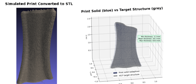
Top Simulated print layer within Simulator to view simulated print process loaded with designed path planning. Bottom Left: full simulated print solid converted to STL after 125 layers, showing characteristic SC3DP layered texture. Right: superimposition of the adaptive print solid (blue) and target concrete form (grey). Wall thickness: min 3.3 mm, mean 26.3 mm, max 64.6 mm.
Conclusion
This work delivers nozzle trajectory planning for SC3DP over complex freeform rebar structures through a four-stage pipeline: autonomous outline detection, nozzle pose definition, feasible orientation planning, and simulation-driven velocity adaptation from prior-layer voxel geometry. Evaluated on the Shimizu Corporation freeform architectural rebar structure, the pipeline produces feasible, executable trajectories, reduces surface height standard deviation by 28.4% (precision), and improves per-layer target coverage by 12.8% (accuracy) relative to a non-adaptive baseline. Because the pipeline operates from a triangulated mesh and a voxel grid without geometry-specific assumptions, it generalizes to arbitrary freeform rebar structures.
Future work includes actively directing spray into rebar-occlusion void zones (currently filled passively), validation across additional rebar geometries to characterize performance across a broader range of structural configurations, and physical print experiments to validate the simulated deposition predictions.
This project developed my expertise in computational geometry (mesh processing, contour extraction, arc-length parameterization), trajectory optimization (potential fields, quaternion interpolation, simulation-in-the-loop planning), and the integration of planning algorithms with physical manufacturing constraints. The methodology generalizes beyond concrete printing to any spray-based coating or deposition application requiring coordinated multi-axis motion planning.
