
Location: Mechanical Engineering, CMU, PA
Timeframe: Spring 2025
Introduction
3D concrete printing enables rapid, cost-effective construction of complex architectural structures while reducing material waste and labor requirements compared to traditional methods. However, to print a structure, the system requires exact waypoints for the print nozzle to follow—errors in the preprocessing pipeline can result in incorrect prints or, worse, structural failures.
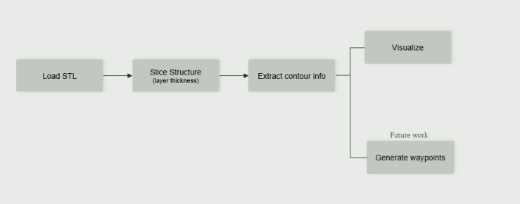
The objective of this project was to create a visualization system that automates the critical preprocessing steps necessary to eventually develop waypoints for concrete 3D printing. Specifically, the system integrates four components: STL loading, uniform slicing, contour extraction, and real-time 3D visualization. By visually confirming each upstream step, we ensure the contour information used for waypoint generation is accurate and reliable.
Design & Development
The system tackles four distinct engineering challenges that increase in computational complexity, each building upon the previous step.
Key design elements included:
- STL Loader: Developed function methods to efficiently convert binary mesh data into usable geometric facets for an OpenGL visualizer. The loader reads file paths, opens in binary mode, iterates through thousands of triangles, and returns a reference structure containing all loaded facets. Users can interact with the model and toggle between wireframe and raw STL views.
- Uniform Slicing Algorithm: Implemented an algorithm that creates evenly-spaced horizontal layers based on user-defined slice thickness. The algorithm generates a list of Z-values representing exact slice heights, then produces contours representing intersection points at each Z-value. This ensures uniform slicing regardless of the model’s geometry—critical for maintaining structural integrity in printed layers.

Uniform Slicing: Mesh surface with evenly-spaced horizontal slice planes based on user-defined layer thickness
- Contour Extraction Function: Created smooth path generation using linear interpolation and mesh edge sorting to establish simulated nozzle positions. The function finds intersection points where mesh edges cross each slice, tracks visited edges, and traverses neighboring polygons sharing those edges until the contour is closed. Smoothing is applied to ensure no jerky paths for waypoints to be sampled from.
- Interactive Visualization Environment: Built a real-time 3D visualization system with comprehensive controls allowing users to rotate, zoom, toggle views (wireframe, solid, slices, contours, path, end effector), and animate nozzle motion along extracted paths.

Interactive Visualization: 3D viewer (left) with comprehensive keyboard controls (right) for rotating, zooming, toggling views, and animating nozzle motion
Challenges I addressed:
- Converting binary STL mesh data into a format usable by OpenGL for visualization of complex models with thousands of triangles
- Ensuring the slicing algorithm handles arbitrary geometries and orientations while maintaining uniform layer thickness
- Implementing robust contour extraction that works on non-symmetric and unrealistic test shapes to prove method robustness
- Integrating all four components into a cohesive pipeline where visualization validates each upstream step
Evaluation
The visualization system successfully integrated all four critical components and validated the preprocessing pipeline for concrete 3D printing. The STL Loader accurately parsed binary mesh data and rendered both wireframe and solid views for user inspection. The Uniform Slicing algorithm consistently produced evenly-spaced layers across various test geometries, including non-symmetric shapes that stress-tested the algorithm’s robustness.
The Contour Extraction function generated smooth, closed paths suitable for future waypoint sampling—tested and validated on intentionally unrealistic shapes to demonstrate the method handles arbitrary geometries. The interactive visualization confirmed correct behavior at each pipeline stage: users can rotate and view the full path, observe the simulated nozzle (red sphere) following smooth continuous motion along extracted contours (light-blue lines), and verify that spacing between layers matches the specified slice thickness.
The modular architecture allows independent verification of each component, making debugging straightforward when issues arise. Visualization served as the primary quality assurance mechanism—if contours appeared incorrect visually, upstream issues could be identified and corrected before waypoint generation.
Conclusion
This project strengthened my skills in computational geometry, real-time 3D visualization with OpenGL, and algorithm design for manufacturing applications. The experience of building a modular pipeline where each component depends on validated upstream inputs reinforced the importance of systematic verification in robotics software.
The system provides a strong pipeline into the planned future work of robust waypoint generation for the concrete spray-printing mobile manipulator I am developing in my research. The techniques developed here—mesh processing, uniform slicing, contour extraction, and interactive visualization—directly inform my research framework for nozzle trajectory planning.
